HISTORICAL DRAWING · 1906
Wing-warping aircraft
What airspeed gives enough idealized lift for an assumed mass?
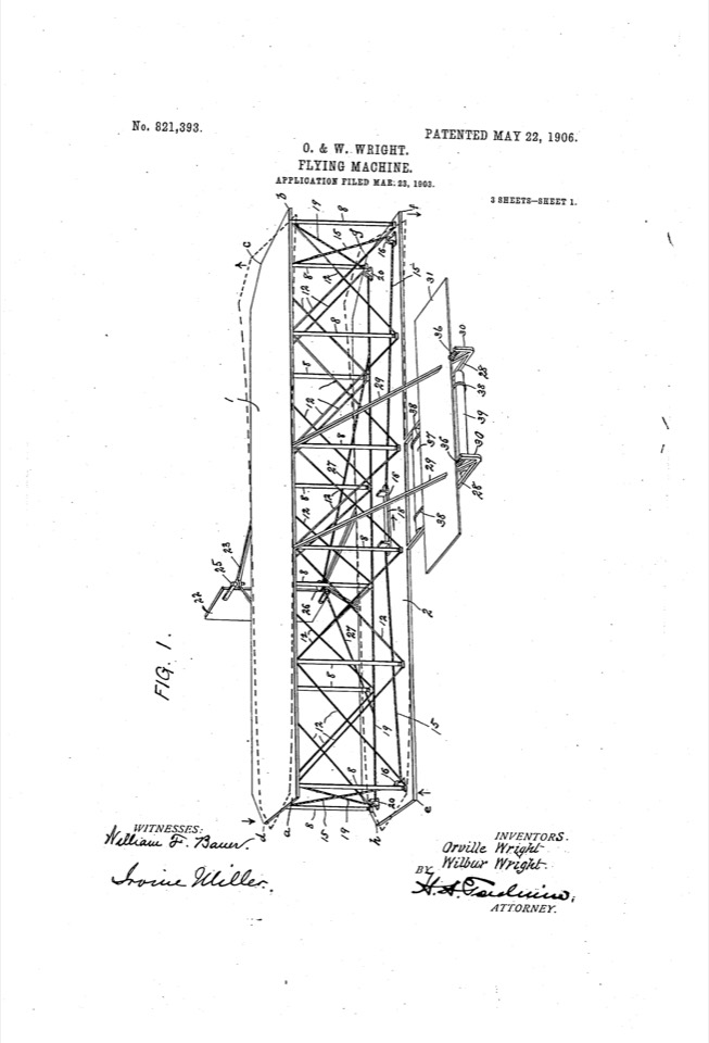
Manual alignment · illustrative vector model · not automatic CAD reconstruction.
A contemporary sketch model
Every number below is a modern illustrative assumption. The historical drawing supplies a question; the source model is an exercise in reasoning about it.
rho = 1.225 kg/m^3 "Illustrative air density"
speed = 12 m/s in 8..18 ± 5% "Illustrative flight speed"
area = 30 m^2 "Assumed lifting area"
CL = 0.8 "Assumed lift coefficient"
mass = 300 kg "Assumed all-up mass"
weight := mass*9.81 m/s^2 [N]
lift := 0.5*rho*speed^2*area*CL [N]
check support: lift >= weight
sweep Speed: speed = 8, 12, 18 m/s
Model limits
Steady lift sizing only; no wing-warping control effectiveness, stall, stability, biplane interference or CFD.
Explore it with your agent
Create a Study, inspect the installed capabilities, and use this source as a starting point. Ask the agent to explain the equations and assumptions, then replace illustrative inputs with measured evidence for your own design.
This example includes a scalar sweep. Use napkin_sketch to add the model and napkin_run to inspect the sweep; the source editor’s scalar comparison view is for simple scenarios.